
Posts in this series so far:
- Introduction
- Setup and schematics
- Making a Breakout Game (coming soon)
Setup and Schematics
In this first blog post on my Arduino Game System project, we will look at the basic schematics and ideas the project is based on.
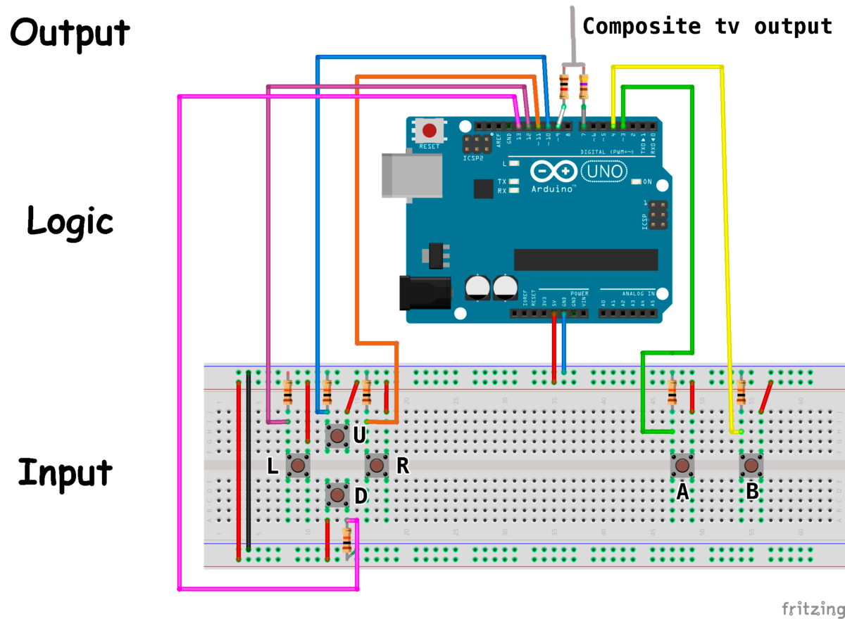
Just like most other Arduino projects, the Game System consists of three parts; input (sensors), logic and output.

Input (sensors)
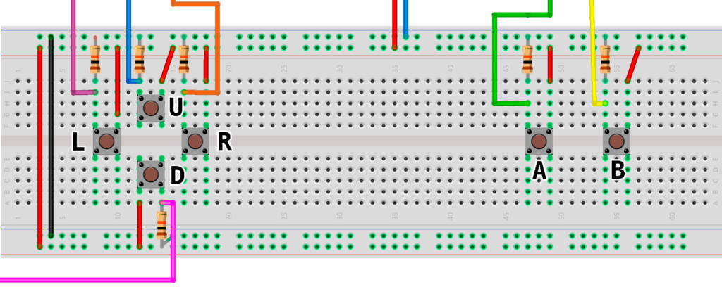
As an input for the Game System we obviously need some buttons, so we can control the players, navigate a menu etc.
In this first version of the Arduino Game System I have chosen to have six different buttons, four movement buttons and two action buttons.
I have used simple tactile switches in this version of the system. Small 6 mm switches for the direction buttons and the larger 10 mm ones for the action buttons. If you decide to make some kind of casing for your Arduino Game System later on, the small switches fits perfectly under a d-pad like the one on the original Game Boy.
Logic
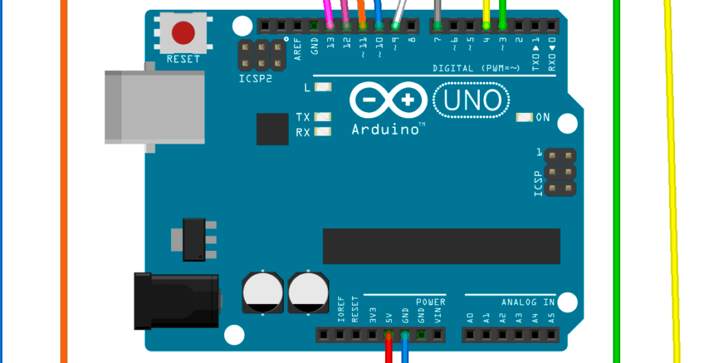
The logic in this system is done on an Arduino Uno. But you can also use other equivalent boards.
For some boards you may have to change the output pins for the composite signal. In this case remember also to change the pin number in the TVout library.
Output
What kind of output you need of course depends on the screen you are going to use.
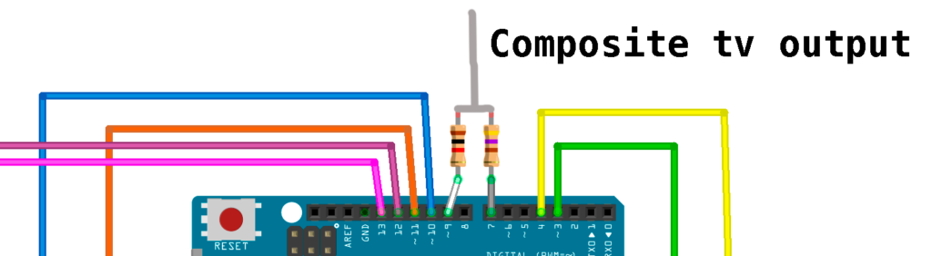
For this first version og my Arduino Game System, I used a small car rear view monitor I found on Amazon. This is a NTSC/PAL TFT screen which requires a composite video input. For this reason this version of the Game System will have a composite tv signal for its output.
To generate the composite signal I used the Arduino TVOut library.
After some time (and a lot of game code) I did have some problem with this library. But for smaller games this if just fine to begin with. I would like to make a new library for composite video signals at some point, but it is not really a priority at the moment.
To generate the composite video signal you need to resistors. Each connected to a digital pin in one end and connected together to form the signal in the other end as shown in the image above.
Which resistors and pins to use are specified here. As stated previously you may have to change the output pins when using other boards than the Arduino Uno.
Making the games
This post was about the setup of the first version of my Arduino Game System.
If you have some experience with Arduino and programming you might be able to make your own game right away.
Here at GitHub I have put a bunch of classes which can be used as inspiration for the basic structure of your game. Please note that this repository is a work in progress and meant for inspiration and testing – it might not all work perfectly together all the time 😉
For those of you who are looking for more help getting started with making Arduino games, I also plan to make a small in-depth blog series on how to make a simple Breakout/Arkanoid game for the first version of my Arduino Game System.
I hope you found this post useful 🙂
/Signe